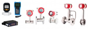
Normal, Illinois Aug 21, 2022 (Issuewire.com) - ATO Flow Meters is part of ATO Automation and is also a direct supplier of ultrasonic flow meters and digital gas flow meters for automation control and monitoring. The commonly used ATO Flow Meters are: turbine flow meter, vortex flow meter, magnetic flow meter, differential pressure flow meter, ultrasonic flow meter, gas flow meter, liquid flow meter, digital gas flow meter, portable flow meter, and mass flow meter.
Flow measurement is one of the components of measurement science and technology, and is closely related to the national economy, national defense construction, and scientific research. Doing this work well will play an important role in ensuring product quality, improving production efficiency, and promoting scientific and technological development. Especially in the current era of energy crisis and increasing automation of industrial production, the status and role of flowmeters in the national economy are more obvious. Flow meters are widely used in various fields of the national economy such as metallurgy, electric power, coal, chemical industry, petroleum, transportation, construction, textile, food, medicine, agriculture, environmental protection, and people's daily life. It is an important tool for developing industrial and agricultural production, saving energy, improving product quality, and improving economic efficiency and management level.
Different types of flow meters have different installation requirements. There are 7 basic requirements for the flowmeter installation:
1. The flow direction is the same, the vortex generating a body of the horizontal pipeline is installed vertically, and the vertical pipeline requires the direction of bottom in and top out.
2. The diameter of the pipe should be the same as the diameter of the instrument input/output, otherwise it should be reduced and expanded. Note that the inner diameter of DIN (German Standard) and ANSI (American Standard) gauges is different.
3. Ensure that the inner walls of the pipes on both sides of the flowmeter are smooth without surfacing.
4. Good alignment is very important.
5. The gasket cannot penetrate into the pipeline.
6. Requirements for the length of the straight pipe section before and after the instrument: the inlet is at least 20D, the outlet is at least 10D, and the straight pipe section is required to be longer at the inlet, when there are multiple elbows or valves.
7. Pipeline vibration requirements: The pipeline should not have strong vibrations. When installing, avoid vibration objects such as motors and water pumps. If necessary, besides the flowmeter, otherwise add support or use hose connections.
Installation precautions for different flow meters:
1. Electromagnetic flowmeter needs to be grounded electrostatically.
2. The mass flow meter needs to be supported to avoid interference caused by vibration.
3. Pay attention to the installation direction of the orifice plate flowmeter, and the inner diameter of the gasket at the flange cannot be smaller than the inner diameter of the pipe, etc.
Requirements for installing straight pipe sections of different flowmeters:
1. Rotameter, the upstream is not less than 0 to 5 times the pipe diameter, and there is no requirement for the downstream;
2. Target flow meter, the upstream is not less than 5 times the pipe diameter, and the downstream is not less than 3 times the pipe diameter;
3. Turbine flow meter, the upstream is not less than 5-20 times the pipe diameter, and the downstream is not less than 3-10 times the pipe diameter;
4. Vortex flow meter, the upstream is not less than 10 to 40 times the pipe diameter, and the downstream is not less than 5 times the pipe diameter;
5. Magnetic flow meter, the upstream is not less than 5-10 times the pipe diameter, and the downstream is not less than 0-5 times the pipe diameter;
6. For the ultrasonic flow meter, the upstream is not less than 10 to 50 times the pipe diameter, and the downstream is not less than 5 times the pipe diameter;
7. Volumetric flowmeter, no requirement;
8. Orifice plate, the upstream is not less than 5-80 times the pipe diameter, and the downstream is not less than 2-8 times the pipe diameter;
9. Nozzle, the upstream is not less than 5~80 times the pipe diameter, and the downstream is not less than 4 times the pipe diameter;
10. For venturi, elbow, and wedge-shaped pipes, the upstream diameter is not less than 5 to 30 times the pipe diameter, and the downstream diameter is not less than 4 times the pipe diameter;
11. For the uniform velocity pipe, the upstream diameter is not less than 3 to 25 times the pipe diameter, and the downstream diameter is not less than 2 to 4 times the pipe diameter.
12. Thermal gas mass flow meter, the upstream is not less than 20 times the pipe diameter, and the downstream is not less than 10 times the pipe diameter.
Media Contact
ATO Flow Meters/Digital Gas Flow Meters lx@ato.com 3094529909 320 S Towanda Ave https://www.ato.com/flow-meters


